
Soteria Dimension Support
Siting, Installation, Maintenance & Troubleshooting

Special consideration must be taken when installing and maintaining the Dimension range of devices. Before installation, commissioning and testing, please carefully review:

Before installing the detector and base, determine the correct location and orientation. Follow the BS5839-1 guidance or local equivalent:
- Site in rooms larger than 1.2m x 1.2m.
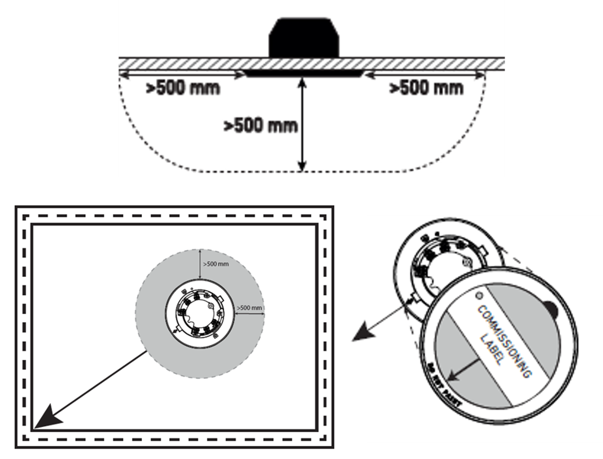
- Position the detector away from ceiling mounted objects such as air conditioning vents, light fittings or security PIR sensors.
- Avoid positioning over doors or where the top of an open door may come within 500mm of the detector.
- Avoid siting in rooms that are exposed to steam, dust or fumes, such as bathrooms, kitchens and rest rooms.

Backbox
After you determine the correct position and orientation of the detector, carefully review the steps in the Backbox IG.
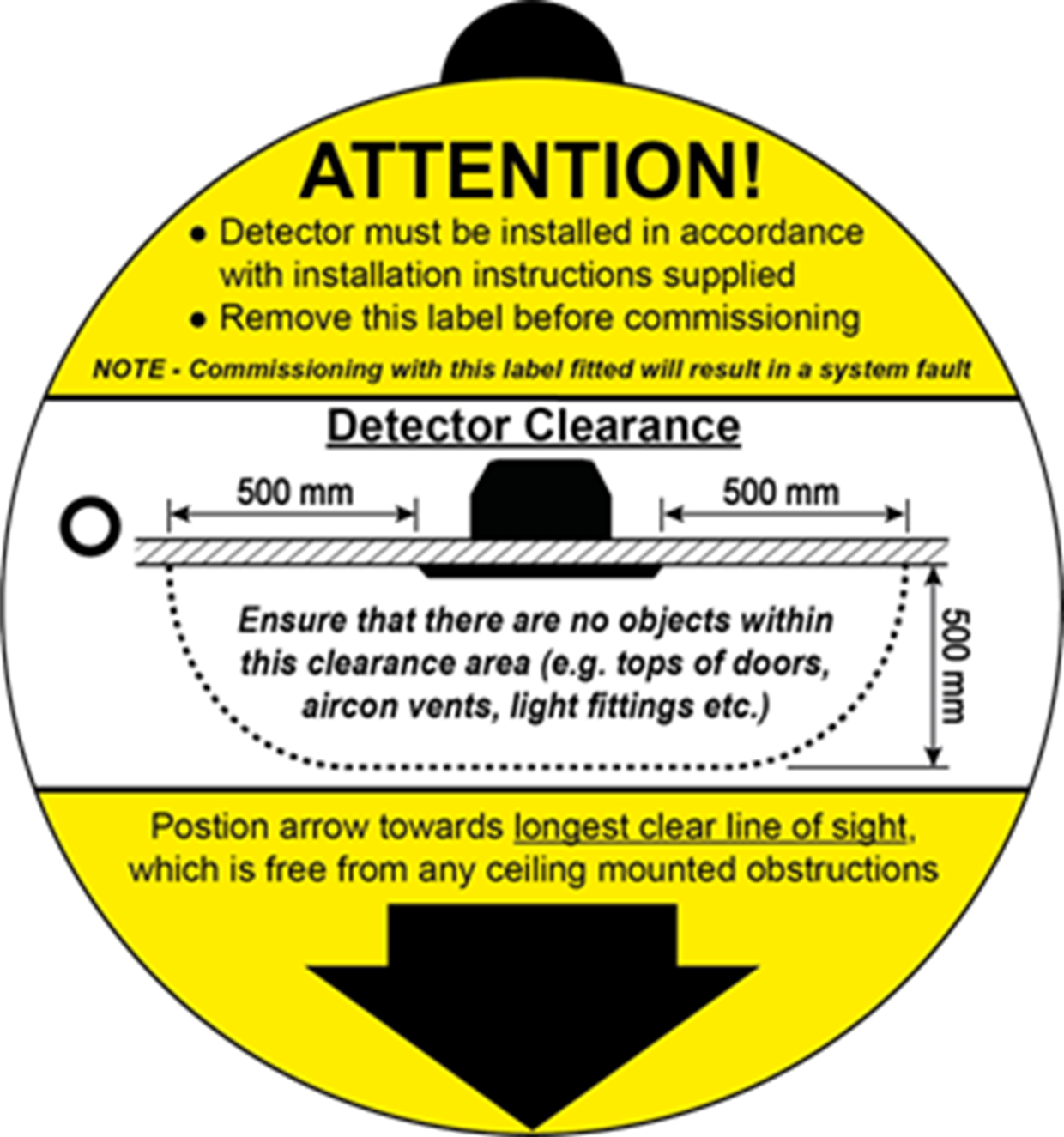
- Install the backbox so the detector has a minimum clearance of 500mm at each side and faces the longest clear line of sight
- The commission label attached on the detector faceplate will help you define the correct orientation of the product.
- Take care not to damage the connector ring or the rest of the backbox when making holes.
- Make sure you connect continuity link position as shown in figure 8.
- Screw down the tabs on the Soteria Dimension Optical detector only as shown in figure 11 – do not screw the tabs on the Specialist variant.
- For ease of installation, we recommend using a wooden plate attached to the false ceiling plate
Installing Soteria Dimension
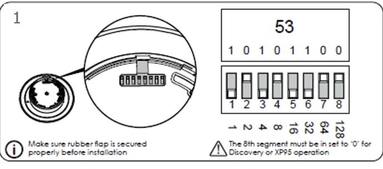
- For Discovery or XP95 operation, ensure the 8th segment in figure 1 is set to ‘0’.
- Make sure the rubber flap is secured properly before the installation.
- Line up the underside arrow with the faceplate hole as shown in figure 3.
- Ensure the grub screw is flush with the faceplate
- Do not remove the commissioning label after the installation
- Line up the underside arrow with the faceplate hole as shown in figure 3
- Important: Do not use clamps, as they may prevent the detector from fully engaging
- For ease of installation, mark the ceiling through the holes of the face plate with a pencil before you drill
- Do not remove the commissioning label after the installation

Commissioning
- The installation of the Soteria Dimension detectors must conform to BS5839-1 standard or local equivalent.
- Remove the commissioning label from the face plate of the detectors – if not removed, the panel will report proximity fault.
- Ensure the windows are kept free from damage, scratches, dirt and fingerprints.
- If the detectors are used with XP95 fire control panels incorporating drift compensation algorithms, these must
- be disabled.

Troubleshooting
| Problem | Possible Cause |
| No response or missing address | Incorrect address setting Incorrect loop wiring Check detector is fully engaged in backbox |
| Fault condition reported | Object blocking windows Proximity fault Commissioning label left on |
| Drift warning or fault | Contaminated windows Incorrect detector orientation |
| Problem | Possible Cause |
| Analogue value unstable | Dual address Loop data fault, data corruption |
| Constant alarm or pre-alarm | Contamination build-up on windows Obscuration of windows |
| Isolator LED on | Short-circuit on loop wiring Wiring reverse polarity Too many devices between isolators |

Testing
- Use the Solo 365, together with the Solo 372 adapter to manually test the product.
- If using FasTest® mode (Core Protocol® only), enable the FasTest® feature on the fire control panel to facilitate quicker testing of detectors.
- FasTest® disables both a portion of the signal processing algorithm and proximity sensing to allow for a faster detector response, while ensuring that the detectors absolute sensitivity remains identical to that of mode 3 (refer to Operating Modes Table).
- Clean the detector lenses with a dry clean cloth after testing.
Maintenance
- Maintenance must be performed in accordance with applicable local codes.
- Always clean detectors with either a dry, lint-free cloth or a non-abrasive cleaning product suitable for use on plastics.
- Before cleaning the detectors, ensure the fire system is suitably isolated.
- Proximity faults may occur during cleaning – they will clear when no objects interfere with the detectors.


For more product information view our product pages:
Or contact our Technical Support Team
Email: techsales@apollo-fire.com
or call +44 (0)23 92442706
8:30am - 4:45pm Monday - Thursday
8:30am - 4:00pm Friday